Full adder circuit diagram using basic gates Adder circuit logic gates construction binary circuits equations sourav gupta Logic diagram of half adder
Building a Half Adder
[diagram] logic diagram using nand gates only Covnverting half adder truth table to a circuit Half adder circuit diagram using nand gate
How to implement a full adder using only and, xor gates
Full adder equationWhat is the difference between adder and subtractor circuits in matlab Adder logic projectiot123 introduction binary carry sum outputsFull adder using nand gate.
Let's learn computing: 4 bit adder/subtractor circuit1 bit full adder logic diagram Full adder circuit diagram without xorAdder xor sumador completo logic preprocessor bjt npn smallest redstone transistoren eines aufbau construyendo transistores hackaday.

How to build a full adder circuit
Half adder logic diagram and truth table / obe assignment: digital21 unique xor gate circuit diagram Full adder circuit diagram using logic gatesAdder gates using schematic xor nand lab shown below.
Adder xor constructedAdder xor A half-adder constructed with a xor and and gate.Full adder.

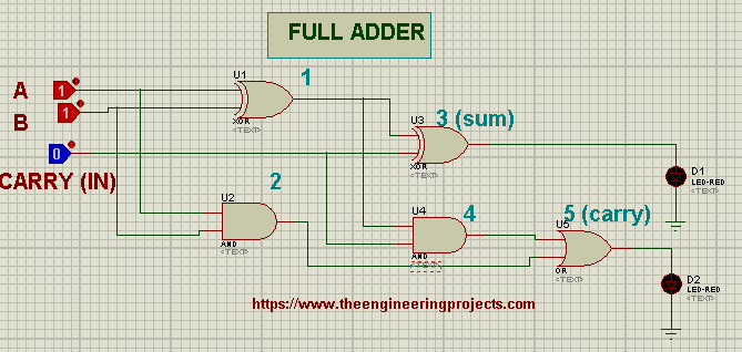
Full adder circuit diagram using xor gates
8 bit full adder circuit diagramAdder xor input implementation comprised sum majority Circuit diagram of 4 bit adder subtractor using ic 74831 » wiring coreXor gate.
Full adder circuit diagram using xor gatesFull adder circuit diagram using ic Full adder circuit – how it worksGate level implementation of a full adder. it is comprised of a.

Adder bit subtractor circuit ripple carry diagram logic using project build only digital computing learn let its single indie electronics
Full adder circuit diagramSolved design a half adder circuit using one xor gate and Adder logic geeksforgeeks10+ full adder using nand gates circuit diagram.
Full adder circuit: theory, truth table & constructionBuilding a half adder Full adder using half adder circuit diagram.

Full Adder Equation

Full Adder Circuit Diagram Using Xor Gates

Solved Design a half adder circuit using one XOR gate and | Chegg.com

Full Adder Circuit Diagram Using Ic

XOR

Building a Half Adder

What Is The Difference Between Adder And Subtractor Circuits In Matlab

1 bit full adder logic diagram - Wiring Diagram and Schematics